Equipment and Layout Options, Side by Side
A Comparison Study puts equipment and layout options for a utility-scale ground-mount PV plant side by side before anything is locked in. Each option is modelled in PVsyst on at least one 3D layout, and the results land in one comparison table: main components, quantities, yield and performance. Preliminary stringing, cabling, road and MV station placement are considered internally, so options are compared as they would actually be built.
Module, inverter and transformer options are set in the quote form. Mounting (fixed-tilt vs. tracker) and orientation (south vs. east-west) comparisons are quoted per project.
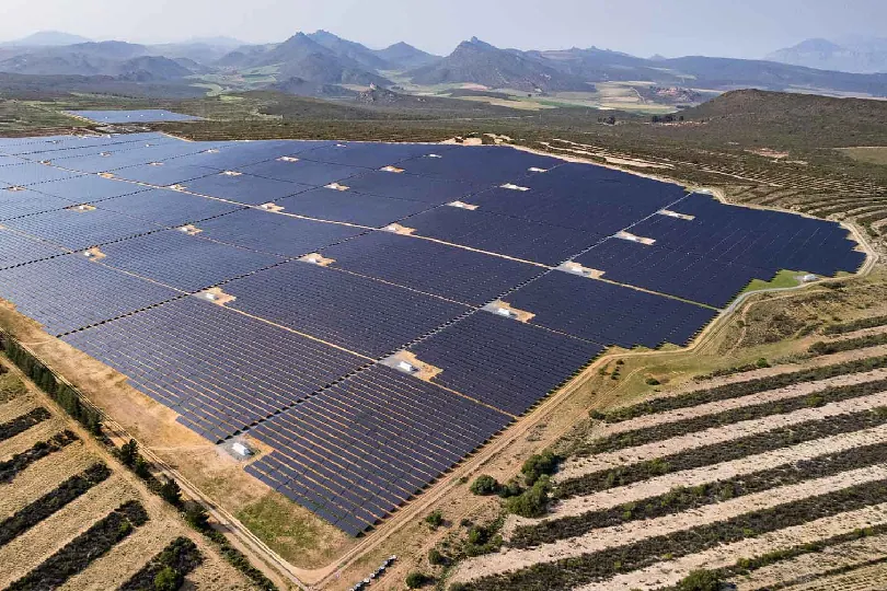
What the Comparison Study Covers
Equipment & Configuration Comparison
Module, inverter and transformer options modelled against each other on the same site.
- Module options
- Inverter options and DC/AC ratio
- Transformer (MV) options
- Yield and performance per option
Electrical Layout per Option
Preliminary stringing, cabling and MV station placement for each option, so electrical losses are compared like for like.
- Preliminary string configuration
- Preliminary cable routing
- MV station placement
- Electrical losses per option
Terrain & Shading
Layouts follow the topography, and shading is modelled for each option.
- Topography-based layout
- Row spacing and inter-row shading
- Shading losses per option
Comparison Table
One Excel with components, quantities, yield and performance for every option — the basis for an equipment decision.
- Components and quantities
- Yield and performance ratio
- Options side by side
How It Works
Options Confirmed
Site, constraints and the options to compare, confirmed before modelling starts.
Modelling
Each option modelled in PVsyst on the 3D layout.
Electrical Layout
Preliminary stringing, cabling and MV station placement for each option.
Comparison Package
Comparison table, PVsyst results and at least one 3D layout.